Optical Interferometers
光学干涉仪
Michael <br> Physics and Astronomy Department, UCLA, Los Angeles, California 90024, USA
迈克尔·余 <br> 加州大学洛杉矶分校物理与天文系,美国加利福尼亚州洛杉矶市90024
(Dated: March 9, 2025)
(日期:2025年3月9日)
I. INTRODUCTION I. 引言
Interferometry, the technique of using patterns produced by superimposed beams to extract information, has had a long and rich history in various fields and is vital to many scientific efforts such as the detection of gravitational waves and incredibly precise metrology. Even today, interferometry is routinely used in many research efforts, technological applications and especially in understanding the quantum nature of our everyday world.
干涉测量技术是利用叠加光束产生的图案来提取信息的技术,在各个领域都有着悠久而丰富的历史,对于引力波探测和高精度计量等许多科学工作都至关重要。即使在今天,干涉测量技术仍然被广泛应用于许多研究工作、技术应用中,特别是在理解我们日常世界的量子本质方面。
Generally speaking, interferometry is the practice in which light from a single, collimated source is split into two (or more) optical paths using mirrors, beamsplitters, substances of various indices of refraction, etc before recombining into a colinear beam and measured. If setup correctly, the interference patterns produced by this seemingly simple technique contains rich information about the two converging beams such as their wavefronts, polarizations, relative phases and wavelength. In this paper in particular, we will be exploring perhaps the two most widely used interferometers: the Mach-Zehnder Interferometer (MZI) and the Michelson Interferometer. The former is routinely used in interferometry as it has the advantage that there is no feedback to the beam source whereas the latter utilizes fewer optical elements and has an important place in the history of disproving the theory of 'aether', the supposed medium that mediates light, in the Michelson-Morley experiment. These interferometers will provide a stepping stone in experimentally understanding and verifying the behavior of light in the semiclassical regime.
一般来说,干涉测量是一种将来自单一准直光源的光分成两条(或更多)光路的实践,这些光路通过镜子、分束器、具有不同折射率的物质等形成,然后重新组合成共线光束并进行测量。如果设置正确,这种看似简单的技术产生的干涉图案包含了关于两束会聚光束的丰富信息,如它们的波前、偏振、相对相位和波长。特别是在本文中,我们将探讨可能是最广泛使用的两种干涉仪:马赫-曾德尔干涉仪(MZI)和迈克尔逊干涉仪。前者因其没有光束源反馈的优势而常用于干涉测量,而后者使用较少的光学元件,并在否定"以太"理论(假定的介导光的媒介)的历史中占有重要地位,即著名的迈克尔逊-莫雷实验。这些干涉仪将为实验性地理解和验证光在半经典区域中的行为提供一个重要的基石。
The remainder of the paper will be structured as follows. Section II will provide a brief background on the theory of interfering waves and the patterns they are expected to produce. Section III and IV will discuss the setup, findings and experimental results of the MachZehnder and Michelson Interferometers respectively. Section V will conclude.
本文的其余部分结构如下。第二节将简要介绍干涉波的理论背景及其预期产生的图案。第三节和第四节将分别讨论马赫-曾德尔干涉仪和迈克尔逊干涉仪的设置、发现和实验结果。第五节将进行总结。
II. THEORY 理论
A. Interference 干涉
好的,我来帮您将内容中的物理名词加粗:
Let us begin with a simple introduction to interferometry in one dimension, the generalization to three dimensions is extended naturally and is further discussed in the following section. Suppose we have a pair of sinusoidal waves propagating in the direction with relative phase . The general equation for their electric fields can be written as
让我们从一维干涉测量的简单介绍开始,这种方法自然可以推广到三维,这将在下一节中进一步讨论。假设我们有一对正弦波在方向传播,它们之间有相对相位。它们的电场的一般方程可以写作:
where k is the wave vector and is the angular frequency of the wave. By the superposition principle, the total electric field can be found by simply adding the electric field amplitudes:
其中k是波矢量,是波的角频率。根据叠加原理,总电场可以通过简单地将电场振幅相加得到:
For a pair of waves that are in phase, that is for , we see that the modulation term in the electric field vanishes: . Under this condition, the waves are said to interfere constructively such that the electric field amplitude is exactly doubled:
对于相位相同的一对波,即(其中),我们可以看到电场中的调制项消失:。在这种条件下,这些波被称为发生建设性干涉,使得电场振幅恰好加倍:
On the other hand, for a pair of waves that are out of phase, that is for , the modulation term goes to 0: . These waves are interfering destructively where the electric field amplitude of one wave is equal and opposite in magnitude to the other and effectively cancel to 0.
另一方面,对于相位相反的一对波,即(其中),调制项变为0:。这些波发生破坏性干涉,其中一个波的电场振幅与另一个波大小相等但方向相反,从而有效地相互抵消为0。
The same idea extends naturally to waves in 3 dimensions: the electric fields simply sum together under the superposition principle and depending on the orientation and relative phases of the waves there will be spots of high intensity when the electric fields add constructively and likewise spots of low intensity when the electric fields cancel out under destructive interference. These patterns of high and low intensity are exactly the fringe patterns that are seen and measured at interferometer outputs which we now discuss in more detail.
这个想法自然可以扩展到三维波:电场根据叠加原理简单相加,根据波的方向和相对相位,当电场建设性叠加时会出现高强度点,同样当电场在破坏性干涉下相互抵消时会出现低强度点。这些高强度和低强度的图案正是在干涉仪输出端观察和测量到的条纹图案,我们现在将更详细地讨论这一点。
III. MACH-ZEHNDER INTERFEROMETER 马赫-曾德尔干涉仪
A. Setup 装置设置
好的,我来帮您将内容中的物理名词加粗:
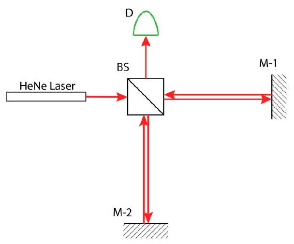
The Mach-Zehnder Interferometer follows a fairly straightfoward setup that consists of 2 beam splitters, 2 mirrors and 2 output ports for measurement, see fig 1. A well collimated beam from a laser source is first sent through a beamsplitter. The resulting perpendicular beams are each reflected off a mirror before entering the second beamsplitter. These two output beams exitting the second and final beamsplitter can then be analyzed visually for fringe patterns or through photodiodes for their total intensities.
马赫-曾德尔干涉仪采用相当简单的设置,由2个分束器、2面镜子和2个用于测量的输出端口组成,如图1所示。来自激光源的准直光束首先通过一个50/50分束器。产生的垂直光束分别经镜面反射后进入第二个分束器。这两束从第二个也是最后一个分束器射出的输出光束可以通过目视观察条纹图案,或通过光电二极管测量其总强度。
It is worth examining why interference occurs at two different output ports or even at all in this setup. The output port in the diagram above detects interference from a) the beam that goes straight through the first beam splitter and reflects off the second and b) the beam that goes reflects off the first beamsplitter and goes through the second. For the output port, the interference pattern emerges from a) the beam that goes straight through both beamsplitters and b) the beam that is reflected off both beamsplitters.
值得研究的是为什么在这个装置中会在两个不同的输出端口产生干涉,或者说为什么会产生干涉。如上图所示,D0输出端口检测到的干涉来自于:a)直接穿过第一个分束器并从第二个分束器反射的光束,以及b)从第一个分束器反射并穿过第二个分束器的光束。对于D1输出端口,干涉图案来自于:a)直接穿过两个分束器的光束,以及b)被两个分束器都反射的光束。
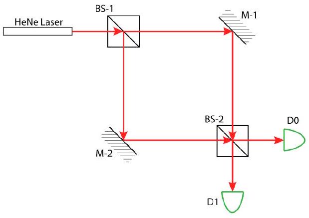
FIG. 1. Mach-Zehnder Interferometer. A well collimated laser is sent through BS1, reflected off mirrors before reconverging in BS2 and measured at photodetectors D0 and D1.
好的,我来帮您将内容中的物理名词加粗:
图1. 马赫-曾德尔干涉仪。准直激光通过BS1,经镜面反射后在BS2中重新会聚,并在光电检测器 D0和D1处进行测量。
For the optical paths that terminate in the output port, they both undergo a phase shift of as there were 2 front surface reflections (from air to glass) in both paths (each contributing a phase shift that occurs when a wave reflects off a medium with higher index of reflection). The optical paths that terminate in the output port, however, obtains a relative phase of through the process. The optical path that goes through both beamsplitters accumulates a phase of following a single reflection from the mirror whereas the optical path that is reflected off both beamsplitters obtains a phase of from the mirror and another phase of from the front facing beamsplitter.
对于终止于D0输出端口的光路,它们都经历了的相移,因为在两条光路中都有2次前表面反射(从空气到玻璃)(当波从具有较高反射率的介质反射时,每次贡献的相移)。然而,终止于D1输出端口的光路通过这个过程获得的相对相位。穿过两个分束器的光路在经过镜面单次反射后累积了的相位,而被两个分束器反射的光路从镜面获得的相位,从正面分束器又获得的相位。
Note, for the other beamsplitter the beam must first enter the glass before reflecting off the double sided mirror, the initial medium (glass) has a higher refractive index than the medium behind the mirror (air) such that no phase shift occurs. That is, the beams obtain a relative phase of when entering . Under ideal circumstances where the output beams are perfectly colinear and the optical path lengths are the same, will experience complete constructive interference whereas will experience complete destructive interference. Of course, in practice, phases arising from optical path length differences must also be taken into account and in general the setup will have some form of nontrivial interference for both output ports.
注意,对于另一个分束器,光束必须先进入玻璃,然后才能从双面镜反射,初始介质(玻璃)的折射率高于镜子后面的介质(空气),因此不会发生相移。也就是说,光束在进入D1时获得的相对相位。在理想情况下,当输出光束完全共线且光程相等时,D0将经历完全建设性干涉,而D1将经历完全破坏性干涉。当然,在实践中,还必须考虑由光程差引起的相位,通常情况下,该装置在两个输出端口都会产生某种形式的非平凡干涉。
B. Interfering Plane Waves 平面波干涉
To understand the fringe patterns that emerge from the Mach-Zehnder, let us now extend our discussion of interference to plane waves in 3 dimensions. Suppose we again have a pair of waves propagating in some direction with wave 2 angled in a slightly different direction with polar and azimuthal angles and . Their electric fields are:
为了理解从马赫-曾德尔干涉仪中产生的条纹图案,让我们现在将干涉的讨论扩展到三维空间中的平面波。假设我们再次有一对波在**+z方向传播,其中波2以略微不同的方向倾斜,具有极角和方位角θ和φ。它们的电场**为:
where and are unit vectors in the direction of propagation. In practice the waves can and often will have a relative phase difference but for the purpose of discussion and ease of calculation, we set the relative phase to 0 and discuss the effects shortly after. By the superposition principle, the total electric field is simply the sum of the constituent waves . The intensity of the waves as they interfere are proportional to their electric fields squared:
其中 和 是传播方向上的单位矢量。在实践中,波通常会有相对相位差,但为了便于讨论和计算,我们将相对相位设为0,并在之后讨论其效应。根据叠加原理,总电场简单地等于组成波的和。波在干涉时的强度与它们的电场平方成正比:
where B is some proportionality constant and is the time average. Evaluating the intensity for at some plane of measurement, say , we have[2]
其中B是某个比例常数,表示时间平均。在某个测量平面上(比如)评估强度,我们得到[2]
好的,我来帮您将内容中的物理名词加粗:
From the modulation term, , we see that fringes occur at locations such that the term inside the outer cosine is for bright fringes and dark fringes. For the interference of 2 plane waves, the resulting interference pattern is a series of bright and dark stripes oriented at some angle with distance between adjacent fringes is given by
从调制项中,我们可以看到在位置处会出现条纹,当外部余弦项内的值为时出现亮条纹,为时出现暗条纹。对于两个平面波的干涉,产生的干涉图案是一系列以角度取向的明暗条纹,相邻条纹之间的距离由下式给出:
See figure 2 for an illustration of the interference process. The attentive reader may recall from earlier than the relative phase between the waves was omitted. This relative phase simply manifests in the wavefronts of one wave being delayed by for relative phase . This phase simply shifts the interference pattern up or down and otherwise has no effect for nonzero . For perfectly colinear beams with , there will be no interference pattern and will affect the overall intensity of the output ports.
参见图2中对干涉过程的说明。细心的读者可能还记得之前我们省略了波之间的相对相位。这个相对相位简单地表现为一个波的波前被延迟了,其中是相对相位。这个相位仅仅使干涉图案上下移动,对于非零的没有其他影响。对于完全共线的光束(),将不会出现干涉图案,而将影响输出端口的总强度。
 好的,我来帮您将内容中的物理名词加粗:
FIG. 2. Depiction of 2 plane wave interference at the output of a MZI. Wave 1 propagates along the +z axis and wave 2 is slightly angled from the +z axis by . The resulting fringe pattern on the surface consists of stripes of light and dark fringes evenly spaced by distance
图2. MZI输出端的两个平面波干涉示意图。波1沿着**+z轴传播,波2相对+z轴有一个小角度的偏转。表面上产生的条纹图案由等间距的明暗条纹**组成。
For the MZI in particular, recall from section IIA that the output ports have a relative phase of . That is, wavefronts of one wave are shifted back by half a wavelength such that the bright regions in the fringe pattern of one output are now the dark regions of the fringe pattern in the other output. We can very clearly see this result experimentally:
特别是对于马赫-曾德尔干涉仪,回顾第IIA节,其输出端口具有相对相位π。也就是说,一个波的波前被移回半个波长,使得一个输出的条纹图案中的亮区现在变成了另一个输出的条纹图案中的暗区。我们可以从实验中清楚地看到这个结果:
C. Beam Alignment 光束对准
好的,我来帮您将内容中的物理名词加粗:
After the MZI is setup such that both output ports have roughly colinear beams, a striped interference pattern as discussed earlier will emerge. Since the distance between adjacent stripes is roughly inversely proportional to the polar angle between the two beams, the number of stripes seen on the outputs give a good indication of alignment. As the beams are better aligned, decreases, the distance between fringes increases and the number of fringes seen in the interference pattern will drop. For perfectly colinear beams at , the distance between fringes goes to infinity and the interference pattern vanishes. For the purpose of alignment, we wish to adjust the setup such that only 3-4 fringes appear. In this case, the beams are well aligned but not perfectly aligned such that the interference pattern disappears entirely.
当马赫-曾德尔干涉仪被设置成两个输出端口具有大致共线的光束时,将出现如前所述的条纹干涉图案。由于相邻条纹之间的距离大致与两束光之间的极角成反比,输出端看到的条纹数量可以很好地指示对准情况。随着光束对准得更好,减小,条纹之间的距离增加,干涉图案中看到的条纹数量将减少。当时,对于完全共线的光束,条纹之间的距离趋于无穷大,干涉图案消失。为了对准的目的,我们希望调整装置使得只出现3-4条条纹。在这种情况下,光束对准得很好但并不完全对准,因此干涉图案不会完全消失。
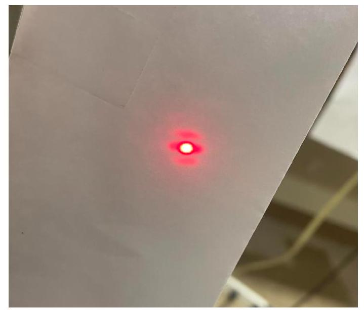
FIG. 3. Experimental fringe pattern at detector 1 of MZI
图3. 马赫-曾德尔干涉仪检测器1处的实验条纹图案
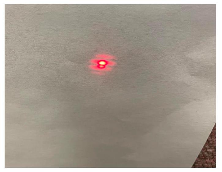
FIG. 4. Experimental fringe pattern at detector 2 of MZI. Note the pattern is complementary to 3
图4. 马赫-曾德尔干涉仪检测器2处的实验条纹图案。注意该图案与图3互补
D. Spherical Wave Interfering with Plane Wave 球面波与平面波的干涉
好的,我来帮您将内容中的物理名词加粗:
Adjusting the MZI such that one arm produces spherical waves, e.g. by adding a lens into one beam path, leads to interesting fringe patterns. From the wavefronts of the constituent beams as depicted in figure 4, the resulting fringe pattern consists of cocentric rings centered at . This can be seen by the fact that the wavefronts of the plane and spherical waves intersect at equal distances from the axis.
调整马赫-曾德尔干涉仪使其一个臂产生球面波,例如通过在一个光束路径中添加透镜,会产生有趣的条纹图案。从图4所示的组成光束的波前可以看出,产生的条纹图案由以为中心的同心环组成。这可以从平面波和球面波的波前在距离**+z轴相等距离处相交的事实**看出。
Using the Pythagorean theorem and noting that , we can compute the radius of the ring from the center:
使用勾股定理并注意到,我们可以计算从中心到第n个环的半径:
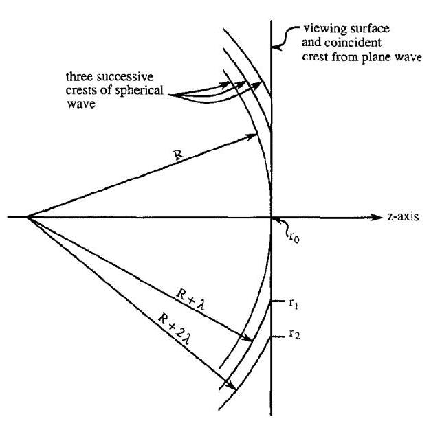
FIG. 5. Depiction of 1 spherical and 1 plane wave interfering. The resulting fringe pattern consists of bright and dark rings centered at the axis. The radius for the nth concentric bright ring is where R is the radius of curvature of the spherical wave.[2]
图5. 1个球面波和1个平面波干涉的示意图。产生的条纹图案由以**+z轴为中心的明暗环组成。第n个同心明环的半径是,其中R是球面波的曲率半径**。[2]
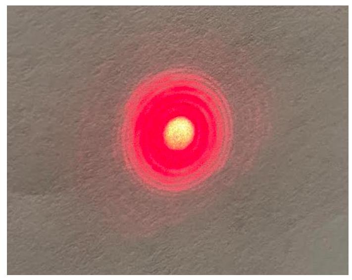
FIG. 6. Experimental fringe pattern of 1 spherical and 1 plane wave interference. The concentric ring pattern agrees well with theoretical prediction.
图6. 1个球面波和1个平面波干涉的实验条纹图案。同心环图案与理论预测吻合良好。
In fact, this setup for the MZI can be utilized to measure the radius of curvature for spherical waves. Knowing the wave length of the laser source, one could measure the radius of 2 distinct rings and thereby extract the radius of curvature for the spherical wave. 事实上,这种马赫-曾德尔干涉仪的装置可以用来测量球面波的曲率半径。已知激光源的波长,可以测量2个不同环的半径,从而提取球面波的曲率半径。
E. Interfering Spherical Waves 球面波干涉
For 2 interfering, perfectly colinear spherical waves, the interference pattern will simply be a patch of constant intensity. Since the wavefront geometry of both waves are exactly the same, save for some possible phase offset, there will be no fringe patterns. However, if the waves are not perfectly colinear, the cocentric ring pattern from
对于2个完全共线的干涉球面波,干涉图案将只是一个恒定强度的区域。由于两个波的波前几何形状完全相同(除了可能存在的相位偏移),不会出现条纹图案。然而,如果这些波不是完全共线的,之前的同心环图案将会
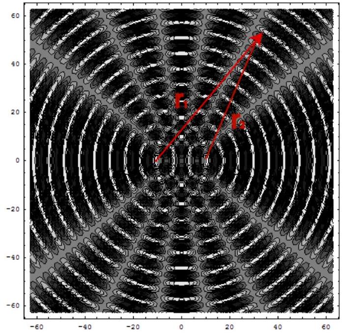
FIG. 7. Wavefronts of 2 slightly separated spherical waves. Notice the 'pinwheel' pattern of constructive and destructive interference. The resulting fringe pattern is again a set a rings but with an alternating pinwheel pattern of light and dark. https://sites.ualberta.ca/~pogosyan/teaching/PHYS_130/ FALL_2010/lectures/lect32/lecture32.html
图7. 2个略微分离的球面波的波前。注意建设性和破坏性干涉形成的"风车"图案。产生的条纹图案再次是一组环,但具有交替的明暗风车图案。
earlier will return with some irregularies. In addition to alternating rings of bright and dark as in the case of spherical and planar interference, there will also be a pinwheel pattern of high and low intensity for 2 spherical wave interference. This arises from the alternating regions in which the two waves interfere either constructively when the wavefronts intersect or destructively when the troughs intersect, see figure 7.
带有一些不规则性地重现。除了像球面和平面干涉情况下的明暗交替环之外,对于2个球面波的干涉还会出现高低强度的风车图案。这是由于两个波在波前相交时发生建设性干涉,而在波谷相交时发生破坏性干涉的交替区域造成的,见图7。
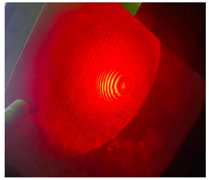
FIG. 8. Experimental fringe pattern of 2 spherical wave interference. The spherical waves are mostly colinear such that the concentric ring pattern is reproduced. Notice, however, that there are slight irregularities around the fringes since both waves are spherical.
图8. 2个球面波干涉的实验条纹图案。球面波基本共线,因此重现了同心环图案。然而,注意到由于两个波都是球面波,条纹周围存在轻微的不规则性。
F. Visibility and Fringe Contrast 可见度和条纹对比度
For perfectly collimated and colinear beams in the absence of noise and back reflection, regions of complete destructive interference would have exactly 0 intensity. Of course, in practice, this is rarely ever the case. Slightly imperfect alignment and stray beams often add noise to the fringe pattern. Fringe contrast, or visibility, V quantifies the quality of the interference pattern and is given by
对于在没有噪声和背反射情况下完全准直和共线的光束,完全破坏性干涉区域的强度应该恰好为0。当然,在实践中,这种情况很少发生。略微不完美的对准和杂散光束经常给条纹图案增加噪声。条纹对比度(或称可见度)V量化了干涉图案的质量,由下式给出:
The optimal fringe contrast arises when the minima have 0 intensity such that . Poor fringe contrast, on the other hand, due to misalignment and noise result in lower visibility.
最佳的条纹对比度出现在最小值的强度为0时,此时。另一方面,由于对准不良和噪声导致的条纹对比度差会降低可见度。
To quantify visibility in this lab in particular, the mirrors were adjusted such that the polar angle between the two beams, , was minimized. From an earlier discussion, this effectively leads to complete constructive interference in one output and complete destructive interference in the other. Due to slight imperfections in the system including stray beams from the lenses and back reflection, the measured maximum and minimum voltages at the photodiodes were 5.4 V and 4.8 V respectively. With a variable impedance of , the output beams had a measured power of and respectively with a visibility of .
为了量化本实验室中的可见度,我们调整了镜子,使两束光束之间的极角最小化。根据之前的讨论,这实际上会导致一个输出端完全建设性干涉,而另一个输出端完全破坏性干涉。由于系统中存在一些轻微的缺陷,包括来自透镜的杂散光束和背反射,在光电二极管处测得的最大和最小电压分别为5.4 V和4.8 V。在的可变阻抗下,输出光束的测量功率分别为和,可见度为。
This rather poor visibility is mainly a result of an imperfect setup in which we were unable to produce complete constructive and destructive interference so that the actual visibility is alot higher as indicated by the sharp fringe contrast of earlier images. Accomplishing perfect alignment using the optical devices at our disposal is quite challenging for the MZI due to the many optical parts and high degree of freedom.
这种相当差的可见度主要是由于设置不完美,我们无法产生完全的建设性和破坏性干涉,因此实际的可见度要高得多,正如早期图像中尖锐的条纹对比度所表明的那样。由于MZI有许多光学部件和很高的自由度,使用我们现有的光学设备实现完美对准是相当具有挑战性的。
G. Polarizers and Quantum Erasure 偏振片和量子擦除
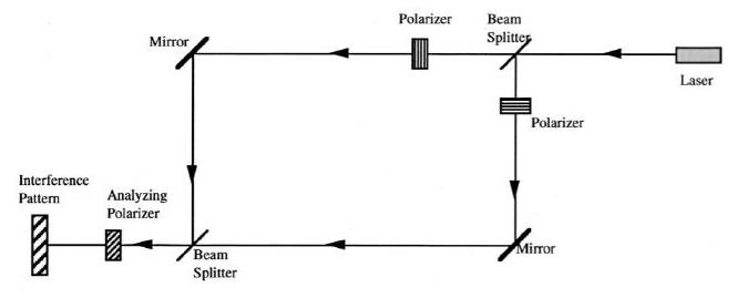
FIG. 9. The MZI with linear polarizers along the input arms. There is an additional analyzing polarizer at the end, before the interference pattern, that can be used to restore the interference effect in what is known as 'quantum erasure'. [3]
图9. 在输入臂上装有线性偏振片的MZI。在干涉图案之前,末端有一个额外的分析偏振片,可用于恢复干涉效应,这就是所谓的'量子擦除'。[3]
Suppose we insert one of two linear, orthogonal polarizers into each of the arms of the MZI as depicted in figure 9. With the polarizers now in the arms of the MZI, one would be able to determine which path a photon took through the system by its polarization alone. As one may expect, the combination of these polarizers destroy the interference pattern normally produced by the MZI:
假设我们如图9所示,在MZI的每个臂中插入两个线性、正交偏振片中的一个。现在MZI的臂中有了偏振片,人们就可以通过光子的偏振来确定它通过系统的路径。正如人们所预料的那样,这些偏振片的组合破坏了MZI通常产生的干涉图案:
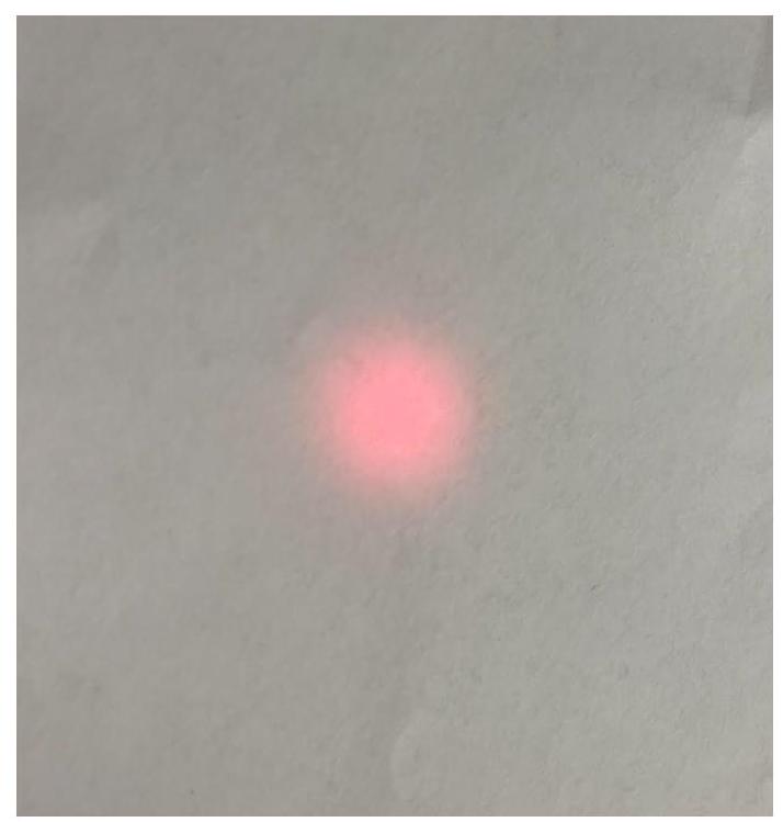
FIG. 10. Experimental interference pattern with 2 orthogonal polarizers inserted in the arms of the MZI. The polarizers encode information about which path photons took and thereby destroy any interference pattern. The overall intensity is reduced by a factor of 2 due to the polarizers.
图10. 在MZI的臂中插入2个正交偏振片的实验干涉图案。偏振片编码了关于光子所走路径的信息,从而破坏了任何干涉图案。由于偏振片的存在,整体强度降低了2倍。
Surprisingly, however, by inserting a third polarizer at the end of the MZI, just before the interference pattern, oriented at a 45 degree angle between the two orthogonal polarizers, the interference pattern is restored!
然而,令人惊讶的是,通过在MZI的末端、干涉图案之前插入第三个偏振片,使其与两个正交偏振片成45度角,干涉图案就恢复了!
How is it that an interference pattern seemingly destroyed by the orthogonal polarizers can be restored by inserting another polarizer at the end of the path? This can be best understood through the idea of quantum measurement. The orthogonal polarizers in the MZI arms will encode, with certainty, which path a photon going through the interferometer has taken. For instance if one arm has a horizontal polarizer and the other a vertical polarizer, a photon that has vertical polarization at the MZI output must have gone through the second arm. That is, 'which-way' information about the photon will be measured at the output. Just as how a photon will not interfere with itself if it has been determined which slit it has gone through in the classic double slit experiment, the photons in the MZI will no longer interference if 'which-way' information has been measured. As we can see in figure 10, photons from the two paths do not interfere and no fringe pattern is produced.
为什么被正交偏振片看似破坏的干涉图案可以通过在路径末端插入另一个偏振片来恢复?这可以通过量子测量的概念来最好地理解。MZI臂中的正交偏振片将确定地编码通过干涉仪的光子所走的路径。例如,如果一个臂有一个水平偏振片,另一个臂有一个垂直偏振片,那么在MZI输出端具有垂直偏振的光子一定经过了第二个臂。也就是说,关于光子的'路径'信息将在输出端被测量。就像在经典的双缝实验中,如果已经确定了光子通过哪个狭缝,它就不会与自己发生干涉一样,如果测量了'路径'信息,MZI中的光子将不再发生干涉。正如我们在图10中看到的,来自两条路径的光子不会发生干涉,也不会产生条纹图案。
[^0]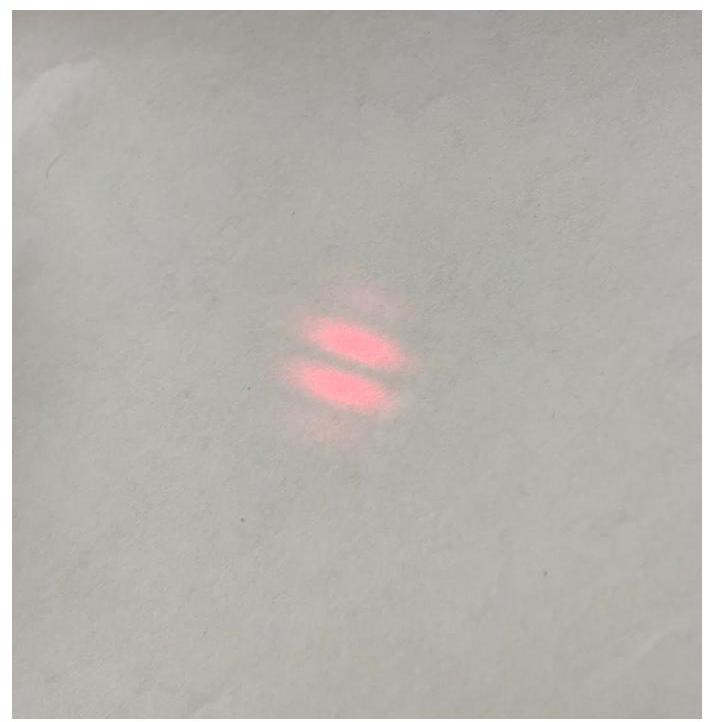
FIG. 11. Experimental interference pattern of 2 orthogonal polarizers in the MZI arms and a 45 degree polarizer just before the interference pattern. By inserting the third polarizer, the interference pattern reappears.
图11. 在MZI臂中插入2个正交偏振片,并在干涉图案之前插入一个45度偏振片的实验干涉图案。通过插入第三个偏振片,干涉图案重新出现。
the second beamsplitter, there is no way to determine with certainty which path a photon has taken. With the final polarization now diagonal, it is now impossible to determine whether the photon has traversed the horizontally or vertically polarized arm as either arm will produce the same diagonal polarization. 'Which-way' information is now effectively erased. The photons are now free to interfere and the fringe pattern is reproduced by the 'quantum eraser', fig 11.
在第二个分束器之后,无法确定光子所走的路径。由于最终的偏振现在是对角线的,因此无法确定光子是通过水平偏振臂还是垂直偏振臂,因为两个臂都会产生相同的对角线偏振。'路径'信息现在被有效地擦除了。光子现在可以自由地干涉,并且条纹图案由'量子擦除器'重现,见图11。
H. Sagnac Interferometer 萨格纳克干涉仪
As a final experiment with the MZI, let us replace the second beamsplitter with a mirror such that the two input beams are sent around the interferometer and back into the original beamsplitter before it is measured at an orthogonal port from the system. In such a setup, the two beams are made to follow the same path but in different directions, ensuring that the optical paths are the same. The phases accrued from reflections, however, are different by between the two paths. The path that goes through the beam splitter twice is has 3 reflections from the mirrors for a total phase accumulated of . The path that is reflected off the beamsplitter twice accumulated a factor of from each of the mirrors but also another factor of from the surface reflection of the beamsplitter itself (reflection in the other surface does not accumulate a phase since it is from glass (higher index) to air (lower index)).
作为MZI的最后一个实验,让我们用镜子替换第二个分束器,使得两个输入光束绕干涉仪传播并返回到原始的分束器,然后从系统的正交端口进行测量。在这种设置中,两个光束被设置为沿着相同的路径但以不同的方向传播,确保光路相同。然而,从反射中累积的相位在两个路径之间相差。两次通过分束器的路径从镜子中获得3次反射,总共累积了的相位。两次从分束器反射的路径从每个镜子中累积了的因子,但也从分束器本身的表面反射中累积了另一个的因子(在另一个表面的反射不会累积相位,因为它是从玻璃(较高折射率)到空气(较低折射率)的)。
好的,我来帮您将这段内容转换为英文名词加粗并添加中文翻译的交替格式:
Under perfect alignment, the output port perpendicular to the laser source should be expected to produce complete destructive interference as discussed earlier. This is indeed the diffraction pattern witnessed experimentally.
在完美对准的情况下,垂直于激光源的输出端口应该会产生完全的破坏性干涉,如前所述。这确实是实验观察到的衍射图案。
One might ask how such an interferometer could be useful if the produced interference pattern was always destructive interference. Since the two beams follow the same path but in opposite directions, a way to introduce a phase difference between the paths is to rotate the interferometer in one fixed direction. The beam path that propagates opposite to the direction of rotation is shorter than the path that propagates in the direction of rotation, thereby producing a nontrival relative phase that can be detected.
有人可能会问,如果产生的干涉图案总是破坏性干涉,这样的干涉仪有什么用。由于两个光束沿着相同的路径但以相反的方向传播,在路径之间引入相位差的一种方法是将干涉仪向一个固定的方向旋转。与旋转方向相反的光束路径比与旋转方向相同的路径短,从而产生可以检测到的非平凡的相对相位。
This exact experiment was setup up by Sagnac in an attempt to prove the existence of aether, an undetectable medium that mediates light. His attempts, as we know, were unsuccessful, but lead us to verify experimentally that the speed of light remains constant in any inertial frame.
Sagnac正是通过这个实验试图证明以太的存在,这是一种不可检测的介质,可以介导光。正如我们所知,他的尝试没有成功,但引导我们通过实验验证了光速在任何惯性参考系中保持不变。
FIG. 12. Michelson interferometer setup. A well collimated beam enters a beam splitter and its resulting beams are reflected off mirrors before reconvering in the same beamsplitter and sent to detector D.[1]
图12. 迈克尔逊干涉仪设置。一束良好的准直光束进入分束器,其产生的光束从镜子反射,然后在同一个分束器中重新会聚并发送到探测器D。[1]
●IV. MICHELSON INTERFEROMETER 迈克尔逊干涉仪
A. Setup 设置
Unlike the MZI, the Michelson interferometer requires only a single beamsplitter and a pair of mirrors. The collaminated beam from the laser source first enters the beamsplitter. The resulting perpendicular beams are each reflected off mirrors before recombining under the initial beamsplitter. The recombined beam can then be analyzed visually for fringe patterns or through a photodiode to measure its intensity.
与MZI不同,迈克尔逊干涉仪只需要一个分束器和一对镜子。来自激光源的准直光束首先进入分束器。产生的垂直光束分别从镜子反射,然后在初始分束器下重新组合。然后可以目视分析重新组合的光束的条纹图案,或者通过光电二极管测量其强度。
Because the Michelson Interferometer only requires a single beamsplitter, alignment here is significantly easier than the MZI due to the lower degrees of freedom. However, the Michelson suffers the disadvantage in that the geometry of the setup makes it easy for a backpropagating beam to be sent into the laser source. A perfectly aligned Michelson where the mirrors are at 90 degrees sends half the recombined beam to the output and the other half to the laser source where it could be reflected off the lens and produce an unwanted source to the interferometer.
由于迈克尔逊干涉仪只需要一个分束器,因此这里的对准比MZI容易得多,因为自由度较低。然而,迈克尔逊干涉仪的缺点在于,设置的几何形状使得反向传播光束很容易被发送到激光源中。完美对准的迈克尔逊干涉仪中,镜子成90度角,将一半的重新组合光束发送到输出端,另一半发送到激光源,在那里它可能会从透镜反射并产生干扰干涉仪的不需要的光源。
The cheapest way to address this concern is to slightly misalign the mirrors such that the beams recombine at a different location in the beamsplitter and the emerging beam slightly misses the laser source, see figure 13.
解决这个问题的最便宜的方法是稍微错位调整镜子,使光束在分束器的不同位置重新组合,并且出射光束稍微错过激光源,见图13。
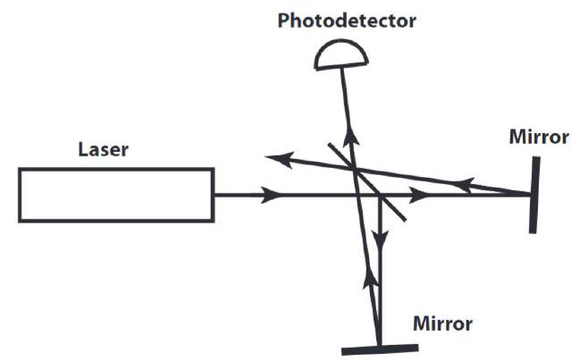
FIG. 13. Slight misalignment of the Michelson interferometer such that the back-propagating beam just barely misses the laser source and does not introduce unwanted beams.
图13. 迈克尔逊干涉仪的轻微错位,使反向传播光束刚好错过激光源,并且不会引入不需要的光束。
B. Piezo-Controller 压电控制器
好的,我来帮您将这段内容转换为英文名词加粗并添加中文翻译的交替格式:
As for the MZI, we want to align the system by adjusting the mirrors such that the number of visible fringes is minimized. As discussed earlier, this maximizes the intensity contrast since the fringes are now so large that it is easy to measure the maximum and minimum intensities by slightly moving the mirrors. To help in slightly adjusting the mirrors, we have applied a piezo-controller on one of the mirrors. The piezo-controller is a simple device that extends a certain distance depending on the applied voltage. For the piezo-controller we used in particular, the device extends on the scale of micrometers (much more sensitive than manually adjusting the mirrors) from a scale of 0 to 150 V . Applying a triangular pulse of 0 to 10 V from a function generator centered at 5 V , where each volt from the function generator corresponds to 10 volts on the piezo-controller, with a frequency of 40 Hz we get a smooth, linear voltage change such that the mirror moves steadily back and forth. The result from the photodiode with such a setup appears as
对于MZI,我们希望通过调整镜子来对准系统,使可见条纹的数量最小化。如前所述,这可以最大化强度对比度,因为条纹现在非常大,通过稍微移动镜子就可以很容易地测量最大和最小强度。为了帮助稍微调整镜子,我们在其中一个镜子上应用了一个压电控制器。压电控制器是一种简单的设备,它根据施加的电压延伸一定的距离。对于我们使用的压电控制器,该设备在0到150V的范围内以微米的尺度延伸(比手动调整镜子要灵敏得多)。从函数发生器施加0到10V的三角波,以5V为中心,其中函数发生器的每个伏特对应于压电控制器上的10伏特,频率为40Hz,我们得到一个平滑的线性电压变化,使镜子稳定地来回移动。使用这种设置的光电二极管的结果如下所示:
As the piezo-controller carefully moves the mirror on the order of micrometers, the optical path length of one arm of the Michelson interferometer goes through several wavelengths such that the beams can alternate between contructive and destructive interference. From an earlier discussion, a path length difference of can be the difference between full constructive or full destructive interference for perfectly colinear beams. We see this result experimentally as the voltages registered from the photodiode rise and fall almost sinusoidally as the mirror is finely moved. Using the piezo-controller, we can get a good estimate of the maximum visibility contrast by carefully adjusting the mirrors manually such that the voltage difference is maximized. By obtaining several visibility estimates for various arm lengths, we can also estimate the coherence length of the laser source!
当压电控制器以微米的量级小心地移动镜子时,迈克尔逊干涉仪的一个臂的光路长度会经过几个波长,使得光束可以在相长干涉和相消干涉之间交替。根据前面的讨论,对于完全共线的光束,的光程差可能是完全相长干涉或完全相消干涉之间的差异。我们在实验中看到,当镜子被精细移动时,从光电二极管记录的电压几乎正弦地上升和下降。使用压电控制器,我们可以通过手动仔细调整镜子来获得最大可见度对比度的良好估计,从而使电压差最大化。通过获得不同臂长的几个可见度估计,我们还可以估计激光源的相干长度!
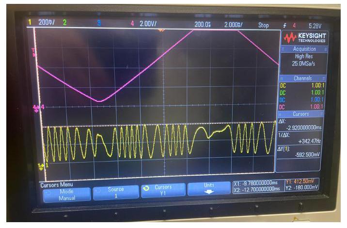
FIG. 14. Oscilloscope readout of the photodiode (yellow) and piezo-controller input voltage (purple). The triangle wave input voltage provides a slow, linear displacement of the attached mirror on the order of micrometers. As the mirror is carefully moved by several wavelengths, the fringe pattern is able to interfere constructively (peaks of yellow) and destructively (troughs of yellow).
图14. 光电二极管(黄色)和压电控制器输入电压(紫色)的示波器读数。三角波输入电压提供了所附镜子以微米为量级的缓慢线性位移。当镜子被小心地移动几个波长时,条纹图案能够相长干涉(黄色峰值)和相消干涉(黄色波谷)。
好的,我来帮您将这段内容转换为英文名词加粗并添加中文翻译的交替格式:
C. Coherence Length 相干长度
The coherence length of a laser is the propagation distance over which the wave can maintain a certain level of coherence. That is, it is the distance in which the wavefronts and electric fields of the wave still roughly follow the form from which it was originally formed. The coherence length itself is usually measured as the optical path length difference that corresponds to 1 /e of the maximum fringe visibility. That is, by adjusting the position of the mirrors and estimating the fringe visibility at each position, we can get an estimate of the coherence length of the laser source. Recall, however, that the Michelson interferometer was slightly misaligned such that the beams don't propagate back into the laser source. Therefore, to find the coherence length for zero misalignment, we must perform a coherence estimate for atleast 2 different misalignments and fit the data back to zero misalignment.
激光的相干长度是指波能够保持一定相干性的传播距离。也就是说,它是波的波前和电场仍然大致遵循其最初形成的形式的距离。相干长度本身通常被测量为对应于最大条纹可见度的1/e的光程差。也就是说,通过调整镜子的位置并估计每个位置的条纹可见度,我们可以得到激光源的相干长度的估计。然而,回想一下,迈克尔逊干涉仪稍微错位,使得光束不会传播回激光源。因此,为了找到零错位的相干长度,我们必须对至少2种不同的错位进行相干估计,并将数据拟合回零错位。
The highest visibility contrast occurs when both arms have the same optical path length. To find the coherence length, we would fix one mirror, change the position of the other mirror and adjust it such that the voltage contrast of the photodetector is maximized. Perform this procedure for several different locations, estimate the visibility for each and fit the results to a Gaussian function. The distance from the peak of the Gaussian to the value in which the function is of its maximum is the coherence length of the particular misalignment. Here the misalignment is characterized by the angle in which the mirrors are misaligned and can be computed by measuring the distance of the back-propagated beam from the laser source and the path length of the fixed mirror.
当两个臂具有相同的光程长度时,会出现最高的可见度对比度。为了找到相干长度,我们会固定一个镜子,改变另一个镜子的位置并调整它,使光电探测器的电压对比度最大化。对几个不同的位置执行此程序,估计每个位置的可见度,并将结果拟合到高斯函数。从高斯的峰值到函数为其最大值的的值的距离是特定错位的相干长度。这里的错位由镜子的错位角度来表征,可以通过测量反向传播光束与激光源的距离以及固定镜子的路径长度来计算。
More precisely, let denote the distance of the backpropagated beam from the laser source and denote the path length to the fixed mirror. Using simple trigonometry, the angle in which the mirror is misaligned is
更准确地说,让表示反向传播光束与激光源的距离,表示到固定镜子的路径长度。使用简单的三角学,镜子的错位角度为
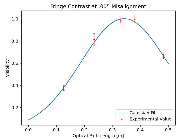
FIG. 15. Gaussian fit of . The maximum visibility is at an optical path length of whereas 1 /e the maximum visibility occurs at an optical path length of .1235 m such that the coherence length is approximately
图15. 的高斯拟合。最大可见度出现在的光程长度处,而1/e的最大可见度出现在.1235 m的光程长度处,因此相干长度大约为
Performing this procedure for several misalignments, we can then perform a linear fit to extract the coherence length at zero misalignment.
对几个不同的错位执行此程序,然后我们可以执行线性拟合以提取零错位时的相干长度。
D. Results 结果
Fitting these results as a function of misalignment, we can extract the coherence length at zero misalignment. Our experimental results indicate that the coherence length of the HeNe laser is approximately 23.67 cm which is pretty close to the average coherence lengths of HeNe lasers at 20 cm .
将这些结果作为错位的函数进行拟合,我们可以提取零错位时的相干长度。我们的实验结果表明,HeNe激光器的相干长度大约为23.67厘米,这与HeNe激光器的平均相干长度20厘米非常接近。
CONCLUSION 结论
Interferometers are an incredibly powerful, yet simple, tool in measuring and analyzing properties of lasers. Here we have demonstrated how the interference patterns from interferometers can be used to determine the type of interfering waves, their propagation direction and orientation as well as the laser wavelength and coherence length. Adjusting the interferometer setups to include polarizers and additional optical components can also be used to rigorously test many theories such as Sagnac's theory of aether and the quantum behavior of photons.
干涉仪是一种非常强大但又简单的工具,用于测量和分析激光的特性。在这里,我们展示了如何使用干涉仪的干涉图案来确定干涉波的类型、它们的传播方向和取向,以及激光波长和相干长度。调整干涉仪设置以包括偏振片和额外的光学元件也可以用来严格测试许多理论,例如萨格纳克的以太理论和光子的量子行为。
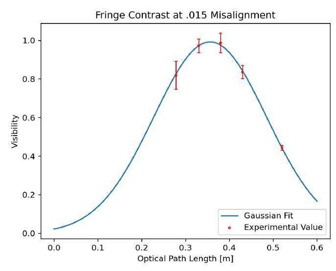
FIG. 16. Gaussian fit of .The maximum visibility is at an optical path length of whereas 1 /e the maximum visibility occurs at an optical path length of .1741 m such that the coherence length is approximately .
图16. 的高斯拟合。最大可见度出现在 的光程长度处,而1/e的最大可见度出现在.1741 m的光程长度处,因此相干长度大约为。
[^0]: If, however, a final 45 degree polarizer is inserted after